

Introduction
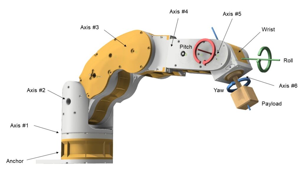
Robotic arms are utilized to position a payload within a 3D space. While a robotic arm with 3 degrees of freedom (DOF) can achieve linear movement along three axes, at least 6 DOF are necessary to enable both linear movement and full rotational control of the payload, including pitch, yaw, and roll (refer to Figure 1).
Problem Statement
A robotic arm is typically anchored at the base and extends outward to position the payload. However, this extension creates significant stress on the axes due to the large torque generated by the weight of both the arm and the payload. If the motors and drives cannot produce enough torque, the robotic arm may stall, collapse, or fail to position the payload accurately. Therefore, reducing the weight of the robotic arm wherever possible is essential.
The wrist contributes significantly to torque on the axes because it is the furthest point from the base (see Figure 1). Reducing the weight of the wrist or moving its center of gravity closer to the base can help reduce stress on the axes. While weight reduction is important, the wrist’s functionality must not be compromised. The wrist needs to remain stiff to ensure precise control of yaw and pitch rotation.
Solution
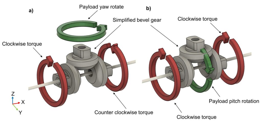
A differential bevel gear mechanism is an effective solution for addressing the weight issues at the wrist. This system consists of three bevel gears positioned at right angles to each other. By adjusting the direction and amount of rotation of the two side gears, the central gear rotates to control yaw, while the entire mechanism can also swivel to provide pitch rotation (see Figure 2).
This mechanism enables two stepper motors to control both the yaw and pitch rotation of the payload simultaneously, ensuring that neither motor is idle at any time. This is advantageous because an idle motor adds unnecessary weight, reducing the efficiency of the robotic arm. Additionally, heavy motors driving the wrist can be positioned closer to the base, which helps reduce the torque on the joints. Finally, the compact design of this mechanism makes it ideal for the confined space at the end of a robotic arm.
Design
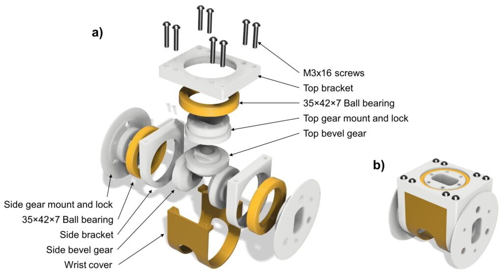
A variety of components, including ball bearings and specially designed brackets, were used to position the bevel gears while allowing them to rotate freely. It is essential that the bevel gears are positioned accurately to minimize backlash and prevent excessive wear. Some specialized brackets, such as the ‘Side gear mount and lock’ (Figure 3), secure the bevel gears and transmit large amounts of torque to them. Another bracket, the ‘Top gear mount and lock,’ extracts torque from the mechanism and transfers it externally, enabling the wrist to lift heavy payloads. Additional brackets, such as the ‘Top bracket’ and ‘Side bracket,’ support large ball bearings and provide anchor points for screws during assembly.
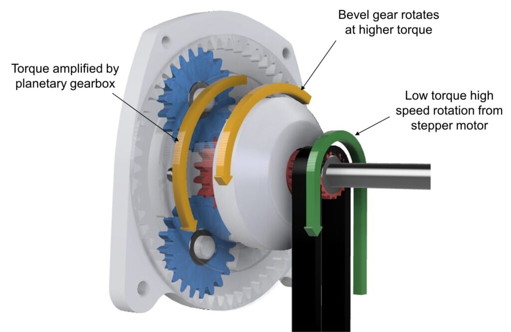
One distinctive feature of this wrist design is the integration of a planetary gearbox within the wrist structure (Figure 5). The planetary gearbox amplifies torque, allowing the wrist to lift heavier payloads (Figure 4). Typically, planetary gearboxes are sold separately and integrated into robotic systems, requiring additional mounting surfaces and interfaces that increase weight and volume. In this design, incorporating the planetary gearbox directly within the wrist allows it to connect seamlessly to the bevel gears, resulting in a more lightweight and compact solution.
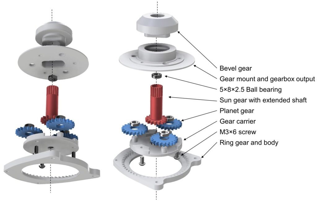
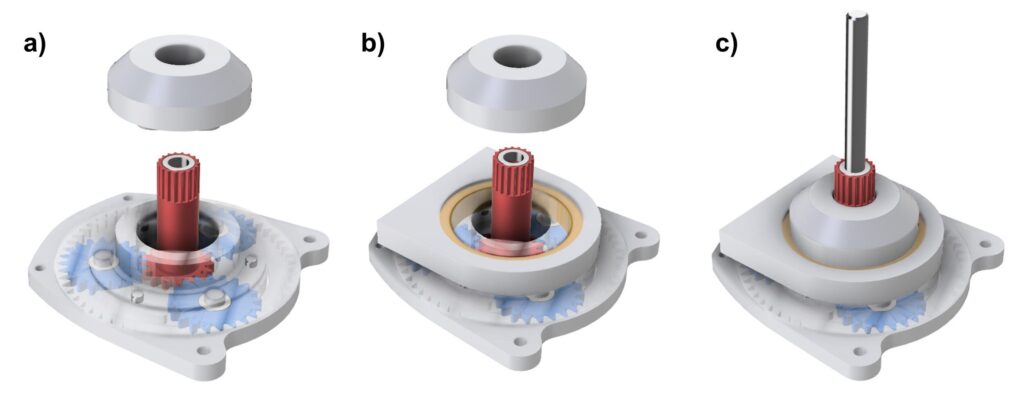
The planetary gearbox inside the wrist includes a sun gear with an extended shaft (red). This shaft passes through a large opening in the bevel gear and reaches the center of the wrist. At the end of the shaft, rough teeth engage with a timing belt, which transfers torque down the shaft to the sun gear. The sun and planetary gears (blue) then rotate within the ring gear, amplifying the torque and transmitting it directly to the bevel gears (Figure 6). This design allows the wrist to be more compact by receiving torque through its center, where ample space is available.
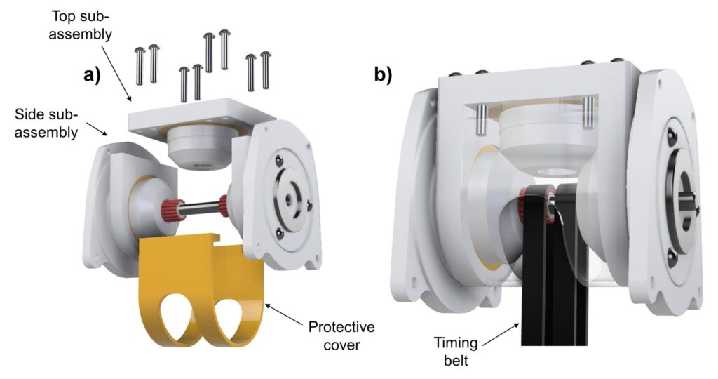
The wrist is composed of three sub-assemblies: two side sub-assemblies containing built-in planetary gearboxes, and one top sub-assembly that holds the bevel gear responsible for lifting heavy loads. These sub-assemblies are fastened together using M3x16 bolts, along with two timing belt loops and a 5mm diameter rod running through the center (Figure 7a). Finally, a protective cover is screwed on to enclose the mechanism, completing the assembly (Figure 7b).
In summary, the design of the wrist is critical because it is positioned at the farthest end of the robotic arm. The design must emphasize compactness and light weight to reduce strain on the joints and avoid the need for larger, heavier motors and gearboxes. Our solution integrates a planetary gearbox directly into the wrist structure, coupling its output directly to the bevel gears. This eliminates extra interfacing surfaces, ensuring the wrist remains both compact and lightweight.