Summary
This article provides a detailed explanation of the design and construction of a 48:1 cycloidal drive, focusing on key components and assembly processes. The cycloidal drive is designed to amplify torque and reduce rotational speed for use in robotics, particularly in robotic arms. The design starts with defining essential parameters such as amplification ratio, eccentricity, and the positioning of cylindrical pins, all while ensuring compactness and ease of manufacturing using a desktop CNC mill.
The cycloidal drive consists of several crucial parts, including a cycloidal disk that wobbles to mesh with cylindrical pins, a load plate with load pins to bear the load, and a top cover that secures the components while preventing dust intrusion. The load plate is constrained in all directions, with a thrust bearing allowing free rotation around the Z-axis. The entire assembly is kept compact by utilizing threaded connections and strategically designed components to maintain precision and reduce the number of parts.
Introduction
A cycloidal drive is a type of speed reducer commonly used in robotics. It decreases the rotational speed of an electric motor while increasing its torque, making it ideal for powering the joints in robotic arms. One notable feature of cycloidal drives is the unique wobbling and meshing motion of the cycloidal disc, which is both functional and visually distinctive.
Cycloidal drives are popular for their high torque amplification ratio, compact size, near-zero backlash, and ease of manufacturing. However, they do have drawbacks, such as vibrations at high rotational speeds, and their performance can be significantly impacted by minor inaccuracies in manufacturing and assembly.
This article aims to provide a comprehensive explanation of the working principle of a cycloidal drive, along with a step-by-step tutorial for designing a 48:1 cycloidal drive using Fusion360 CAD modeling software.
Working Principles
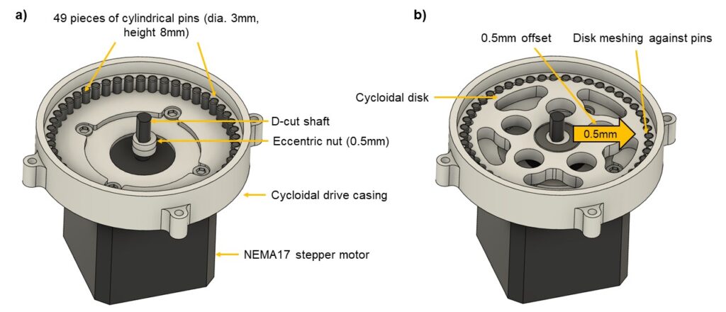
At the core of a cycloidal drive is a disk with a cycloidal profile, mounted off-center on the input shaft. As the shaft rotates, the disk meshes with a series of cylindrical pins evenly distributed around its perimeter (Figure 1b). The system includes one extra pin (49 pins) compared to the number of teeth on the disk (48 teeth), causing the disk to lag by one tooth with each full rotation of the shaft. For the disk to return to its original position, the shaft must complete 48 full revolutions.
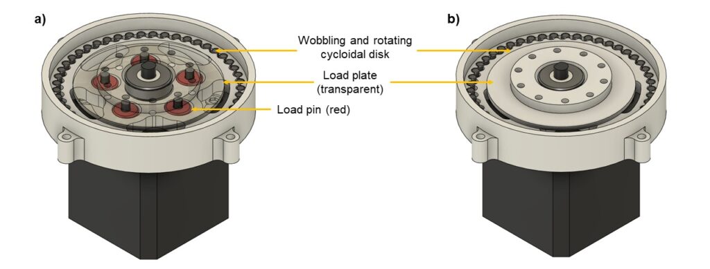
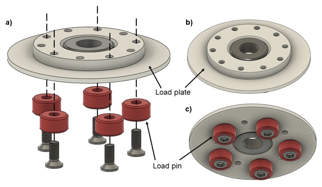
As the disk wobbles and slowly rotates, it presses against another set of 5 pins connected to a load-bearing plate, allowing the plate to rotate concentrically with the cycloidal drive (Figure 2a). This load-bearing plate also serves as the output shaft, which can be connected to other components within a robotic arm to transfer the amplified torque to where it is needed (Figure 2b).
Cycloidal Drive Design Tutorial
The two main design objectives for this 48:1 cycloidal drive are: 1) to create a highly compact drive, and 2) to ensure it is easy to manufacture using a desktop CNC mill. A compact design reduces weight, enhancing the robotic arm’s payload capacity and reach, while designing for ease of manufacturing helps keep production costs low.
The first step in designing a complex mechanism is to identify a component with fixed dimensions that is difficult to modify, and use it as the starting point for the design process. For the 48:1 cycloidal drive, the design will begin with the NEMA17 stepper motor and its D-cut shaft.
Designing The Eccentric Nut
According to documentation, a NEMA17 motor has screw holes arranged in a square with an edge length of 31mm, a 42x42mm body, and a step profile at the top with a diameter of 23mm. The D-cut shaft is 5mm in diameter, with a flat section 1mm from its circumference. To drive the cycloidal disk, the shaft must offset the disk by 0.5mm to mesh with a series of cylindrical pins positioned around its perimeter. This can be achieved using a simple eccentric nut mounted onto the NEMA17 stepper motor’s shaft (Figure 1a).

The eccentricity is set at 0.5mm due to space limitations (Figure 3a), as the design must also accommodate an 8x16x5mm ball bearing. A larger eccentricity is not recommended because it would result in greater movement of the cycloidal disk, requiring a larger casing to accommodate the additional motion. While a larger eccentricity can improve meshing and reduce the risk of disk slippage in high-torque applications, the trade-off in size makes it less practical.
Designing the Casing
The casing of the cycloidal drive serves several functions: 1) it holds 49 pieces of 3mm cylindrical pins in place, 2) it attaches to the NEMA17 stepper motor, 3) it provides space for the cycloidal disk to wobble, and 4) it allows a cover to be secured to the casing.
The 49 cylindrical pins are evenly positioned along a circular path within the casing to allow the cycloidal disk to mesh with them. Ideally, the pins should be placed closely to keep the cycloidal drive as compact as possible, but there must be enough space for the disk to fully mesh. Given the eccentricity of 0.5mm, the spacing between each pair of pins should be about twice that, or around 1mm. Additionally, enough material needs to be left between the pins to provide mechanical support under high torque conditions. The final pin positions were determined through trial and error to achieve the necessary spacing of roughly twice the eccentricity (Figure 4).

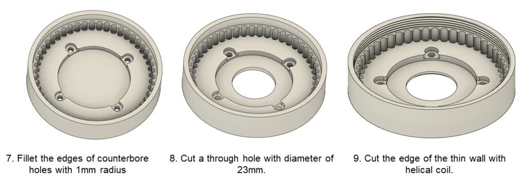
The design of the cycloidal drive casing begins with a flat cylinder, into which pockets are cut to create space for the cover to fit. A thin wall, 2.5mm thick, provides structural support for the final drive cover. Additionally, 49 holes with a 3mm diameter and 8mm depth are drilled into the casing to hold the cylindrical pins in place.

Next, cut a 62mm diameter pocket with a depth of 5mm to provide space for the cycloidal disk to wobble. Then, cut a 39mm diameter pocket with a depth of 3mm to accommodate the torque pins as they are pushed by the cycloidal disk. Finally, create four counterbore holes for M3 screws to allow attachment to the stepper motor.

Fillet the edges of the counterbore holes with a 1mm radius to enlarge them and ensure sufficient clearance for CNC milling. Cut a 23mm diameter through-hole to accommodate the stepper motor and its 23mm stepped profile. Finally, add threads to the thin wall for securing the final casing with a screw-on cover. This reduces the number of parts needed, as no additional screws are required, and helps keep the drive compact by eliminating the need for extra space for screw holes.
Design the Cycloidal Disk
To start designing the cycloidal disk, four key parameters must be defined in advance: a) amplification ratio, b) eccentricity, c) cylindrical pin diameter, and d) cylindrical pin positions. These parameters were outlined earlier in this article:
- Amplification ratio = 48 to 1
- Eccentricity = 0.5mm
- Cylindrical pin diameter = 3mm
- Cylindrical pin position = diameter 62mm
Step 1: Draw a circle with radius of 31mm since the pins are placed 31mm away from shaft.
Step 2: Draw a horizontal line from the centre to the edge. Divide the horizontal line into 48+1=49 portions where the long segment takes up 49 portion at 30.367mm while the short segment takes up 1 portion at 0.622mm.
Step 3: draw another big circle from the centre to the edge of long segment so that its radius is at 30.367mm.

Step 4: Duplicate long segment around the centre point. Each long segment is separated exactly 0.5deg from one another. There should be 16 long segment and the last one is at 7.5deg. The last one is at 7.5 deg because 360deg/48 = 7.5deg.

Step 5: These duplicated long segment are now known as primary lines. Each primary lines had its own angle between 0deg to 7.5deg and it will be used to draw secondary lines. The angle for secondary lines are simple the angle of primary line multiply by 48+1= 49 times. For example, secondary line stretching out from primary line #7 with an angle of 3.0deg will have an angle of 3.0*49=147deg. Repeat it till all the primary lines are connected to secondary lines.
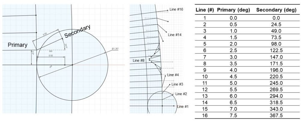
Step 6: Connect the ends of all secondary lines with spline line.
Step 7: offset the spline profile by 1.5mm which is half the diameter of pin at 3.0mm.
Step 8: duplicate the offset profile around the center 48 times to enclose an area. Select the area and extrude 5mm.

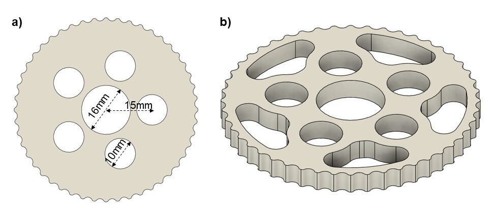
Step 9: The disk will wobble with an eccentricity of 0.5mm and will be pushing again 5 pieces of load pins. The load pins have a diameter of 9.0mm and to allow the disk to wobble on all size, 10.0mm holes are added to the disk. For fitting of ball bearing, a hole of 16mm is created.
Step 10: This is an optional step to reduce the weight of the cycloidal disk by cutting out excess materials. This reduces the weight of cycloidal disk and minimize vibration while the cycloidal drive wobbles during operation. However, excess removal of material will reduce the stiffness of the cycloidal disk and cause it the bend end slip during high torque scenarios.
Designing Load bearing Plate and Pin
The cycloidal disk wobbles as it rotates, making it unsuitable for bearing loads. A secondary structure, consisting of a load plate and load pins, is required to support the load. This simple mechanism involves attaching 5 load pins to the underside of the load plate using threaded screw holes (Figure 6a). Along with the load plate, the pins fit into 10mm holes on the cycloidal disk and are guided along a circular path by the disk’s movement. Additional threaded screw holes allow external structures to be connected to the cycloidal drive.
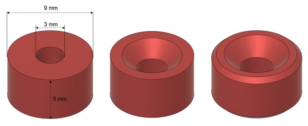
The load pins are simple cylinders with a 9mm outer diameter and a 3mm through-hole. Chamfers are added to the through-hole to allow a countersunk screw to sit flush and ensure precise alignment of the load pin. Smaller chamfers are also added to the outer edges, making it easier for the load pin to slide into the cycloidal disk (Figure 7).
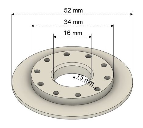
Load plate consists of threaded screw holes arranged 15mm away from the center to allow load pins to be attached to it. Another set of threaded screw holes allow external structures to be attached to the cycloidal drive. A thin disk along the peripheral is for holding a thrust bearing with external diameter of 52mm and internal diameter of 35mm (Figure 9).
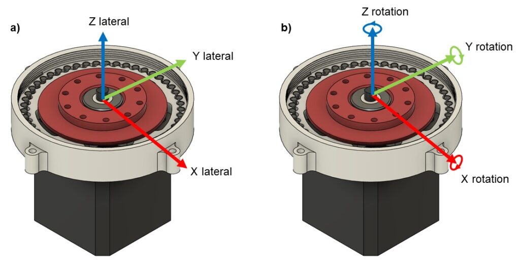
The load plate serves as an anchor for external structures and must be constrained laterally in the X, Y, and Z directions (Figure 8a), as well as rotationally around the X and Y axes, while still allowing free rotation around the Z-axis (Figure 8b). A small pin, with an outer diameter of 8mm and an inner diameter of 5mm, is used to constrain the load plate and ball bearing laterally in the X and Y directions. A thrust bearing placed on top of the load plate constrains it laterally in the Z direction and prevents rotation around the X and Y axes. The thrust bearing also enables free rotation around the Z-axis, ensuring the cycloidal drive operates as intended.
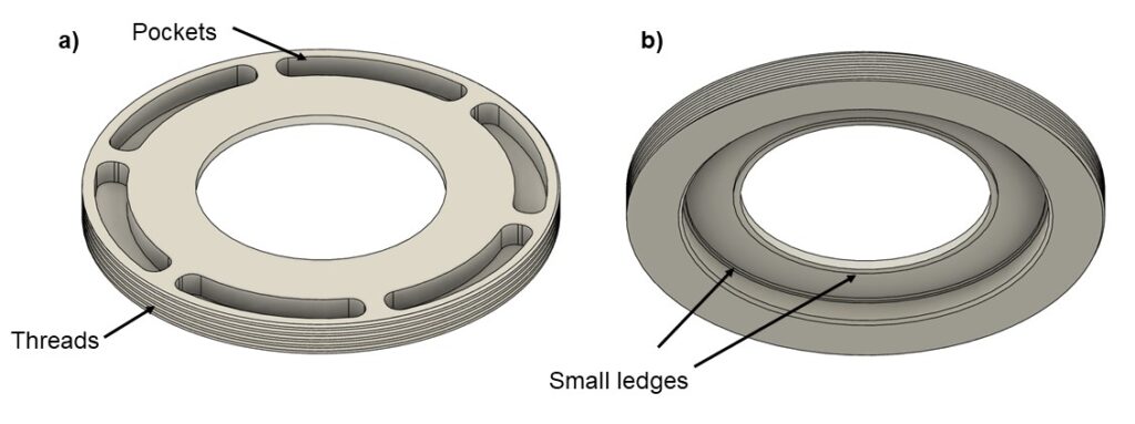
The top cover is the final component of the cycloidal drive. It features a small pocket at the top to reduce weight and provides anchor points for tools to screw it into place (Figure 10a). Threads along its sides allow it to be securely screwed into the cycloidal drive casing. Additionally, small ledges beneath the cover elevate the thrust bearing, enabling it to rotate freely within the casing (Figure 10b).
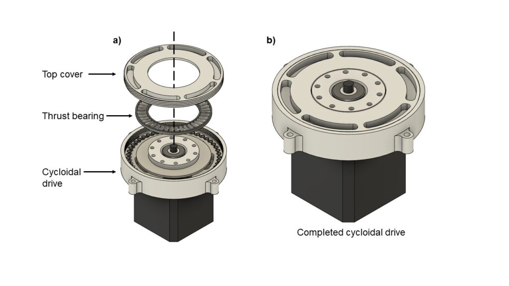
Once the thrust bearing is placed on the load plate, the top cover can be positioned over it and screwed into place. Securing the top cover not only holds all the components together but also prevents dust from entering the cycloidal drive (Figure 11).
Download Design Files
Download the design files here -> Click Here to Begin Downloads
STEP, STL and Fusion 360 design and assembly files are included.
Discover how you can easily turn your design ideas into reality with Fusion360 Premium courses at zero costs. Click Here to Start Lessons #1
List of components needed:
1. NEMA17 stepper motor x1
2. 8x16x5mm ball bearing (688) x 2
3. M3x8 countersunk screws x 9
4.Thrust Bearing (3552) 2mm x 1
5. M3x8 dowel pins x 49
6. 5x8x10mm nylon spacer x 1
Watch detailed assembly guide below:


2 comments
Thanks for the comprehensive article.
This is by far the best 3d printable cycloidal gearbox/article I have come across so thank you very much.
I’m having some issues finding M3x8 dowel pins as they are simply too expensive. Is it possible to extrude the holes you have made for the dowel pins upwards to make it seems like the pins are there?
I’m sure it will add to friction and wear down faster but its kind of my only option
Comments are closed.