Slew bearings are a type of compact bearing that is capable of constricting lateral movements in X,Y and Z axis while allowing free rotation in XY plane. This is great as compared to other bearings where we need to create additional structure to constrains its movement.
Slew bearings are often used in excavators which allows them to rotate and at the same time bears large amount of load. Whether you are a designer or hobbyist, the flat nature of slew bearing might come in handy some day.
In today tutorial, we will explore how the slew bearing is designed for functions and designed to be easily 3D-printed. We will also use the same concept to explore designing models with parametric.
Slew bearing comes in many different shape and sizes. The good thing about 3D-printing is the ability to customize slew bearing to suit your own needs at no additional costs and you need not rely on standard off-the shelves bearing and forced to make design changes to accomodate to what’s is available at the market.
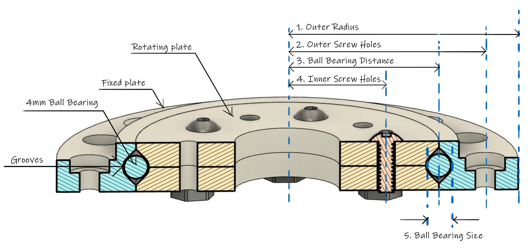
There are several key parameters to take note for the slew bearings. For this tutorial we will be looking at just 5 key parameters you need to take note when designing a slew bearing as follows. And we will specify some dimensions for those key parameters for this tutorial. Feel free to change them to cater for your own requirements.
Outer radius : 35mm
Outer Screw Holes : 30mm
Ball Bearing Distance : 23mm
Inner screw holes : 15mm
Ball bearing size : 4mm
Figure 1. Important parameters for a slew bearing.
Step 1: Find your design constrains.
As this slew bearing will be mounted to a casing, we need to identify the location of the screw holes at the casing so we can add in screw holes on our slew bearing. For this casing, the outer screw holes is identified to be 30mm away from the center.
Step 2: Draw cross section of a M3 screw hole with counterbore
The external screw hole location is the anchor dimension (means it cant be changed easily) and hence we need to arrange the remaining features of slew bearing around it. A sketch will help us identify any overlaps or collisions.
Step 3: Specify screw hole position from center
As discovered earlier, we need the screw holes to be 30mm away from the center so it is inline with the screw holes at the casing below.
Step 4: Specify outer radius of slew bearing
Similarly, the slew bearing need to fit into another casing below and we are specifying the outer radius so that it can fit in.
Step 5: Sketching grooves
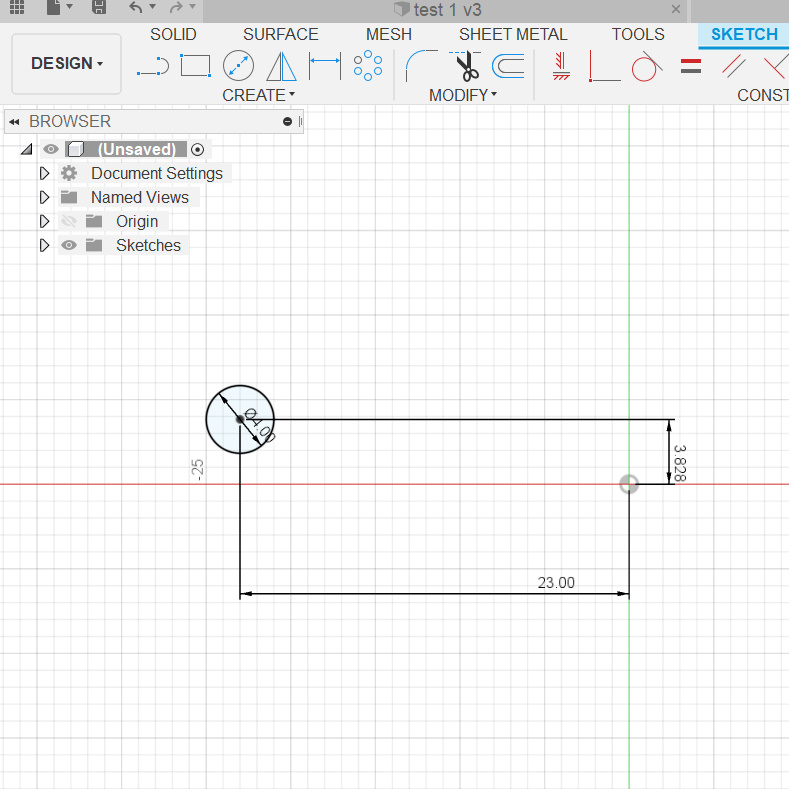
Grooves are important because they hold the ball bearing and specifying the dimension well will help makes the ball bearing smooth. As we will be using a 4mm ball bearing. we will create a 4mm circle. We will also create a 45 degrees line to avoid steep overhang that will need to be supported by support structures.
Step 6: Further specifying grooves
The groove need to have at least 1mm of material below for stiffness so that the slew bearing can bear large amount of weight. We will be drawing a vertical line from circle center and add another 1mm at the location where it intersects with 45 degrees line.
Step 7: Specifying position of ball bearing groove
As mentioned earlier, the outer screw holes are the anchor dimension and we will be arranging the features around the screw holes. In this case, we will be positioning the groove about 4mm away from the screw holes.
Step 8: Mirroring to complete the grooves
A simple step of drawing a horizontal line from circle center and using it to duplicate the bottom half of the grooves to top part of the grooves. In this step, you can see why it is important to have a 45 degrees slant to avoid a overhang which will be hard to 3D print.
Step 9: Enclosing the sketch
Just adding some lines to create an enclosed area around the sketches to create cross section for revolve extrude to create the fixed plate.
Step 10: Revolve extrude
In this step we will turn our 2D sketches into 3D solid. We can easily do it with revolve extrude. We select the enclosed area and revolve it around the Z axis.
Step 11: Creating external screw holes
let’s create some screw holes on the external side of the fixed plate. This is a place for putting in M3x16 (3mm diameter and 16mm in length) screws. We are also going to create a counterbore for the screw caps sit flushed inside.
Step 12: Duplicating the screw holes
We will use circular pattern to create another 15 additional screws hole around the rim of the fixed plate.
Step 13: Checking the dimensions
The slew bearing was meant to be mounted onto another casing. So we added it to the casing and aligned them to check that all the screw holes are in place.
Step 14: Specify groove position for sliding plate
We get our groove position based on the fixed plate that we had designed earlier. The grooves need to match up so that the slewing bearing wont be too loose and start wobbling.
Step 15: More sketching of the groove
A 45 degree slant is added to the groove and constrained accordingly.
Step 16: Enclosing an area
After we define the grooves, we are going to create an enclosed area so that we can do a revolve extrude to create 3D model of the rotating plate.
Step 17: Revolve extrude
Select the enclosed area and do a revolve extrude around Z-axis to create a 3D model.
Step 18: Create holes for screws and bearings
Create holes on the top surface of the sliding plate for screws and bearings (optional)
Step 19: Duplicate 9 more screw holes
Use circular pattern to generate 8 more screw holes to create 10 holes. You can increase or reduce the holes depending on your requirements.
Step 20: Put both sliding and fixed plate together
Put the sliding and fixed plate together for checking the dimensions. I have turned on cross section analysis and you have a better look at the grooves.
Step 21: You Completed the tutorial
Great for following this tutorial to the end. We have completed the tutorial for the slew bearing and we will proceed to 3D-printing them out. In the next chapter, we will explore some minor problems with 3D-printing and explore drawing your model with parametric to make it super easy to change dimensions efficiently. Stay Tuned!


2 comments
Nice, it looks very compact.
Hi Matteo,
Thanks! If you like compact mechanism, you can check out my latest article on a compact cycloidal drive. you can download the design files here https://www.ewhiteowls.com/2022/02/the-ultimate-guide-to-design-cycloidal-drives-the-beating-heart-of-robotic-arms/
Comments are closed.