

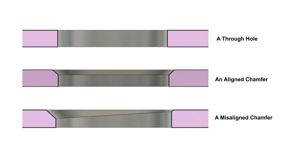
More often than not, you will face components that need to be milled on both sides and the features had to be aligned perfectly. So how you find your reference again after releasing a part from the clamp? For example, how do you align a circular chamfering tool path exactly at the circle center so you could create a perfect chamfer?
While there are other means to do find circle centers with touch probes, they are expensive for desktop CNC milling. Most of them are designed for industrial CNC milling equipment with large shank size and you cannot mount it onto your desktop CNC. Soft jaws on the other hand are rather time-consuming and not worth the effort if you are making just 2-3 identical parts.
Thankfully, most portable USB microscope are affordable and with some simple 3Dprinted brackets and free software, you can find part edges quickly with your desktop CNC equipment.
Step #1 : Figure out a place to mount a microscope.
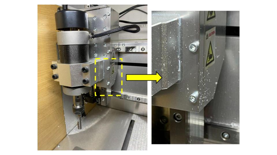
After probing around my desktop CNC, I figured out that the bottom two screw at the back plate is ideal. It is important to know that CNC equipment are highly calibrated down to the microns. Its best not to even remove any screw that holds on to your spindle or linear rails. Try to look for screws that are just for holding simple parts together.
Step 2: Mount a 3Dprinted bracket onto your desktop CNC equipment
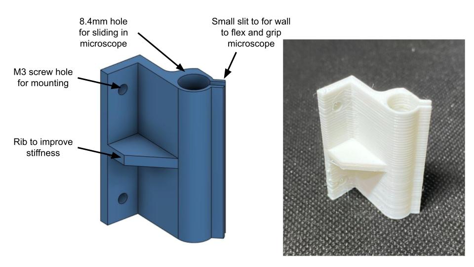
Clean up the brackets and mount it onto the Z table. Do not have to worry precision, we will calibrate it later
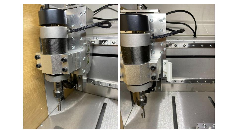
Step 3: Secure a microscope onto the bracket
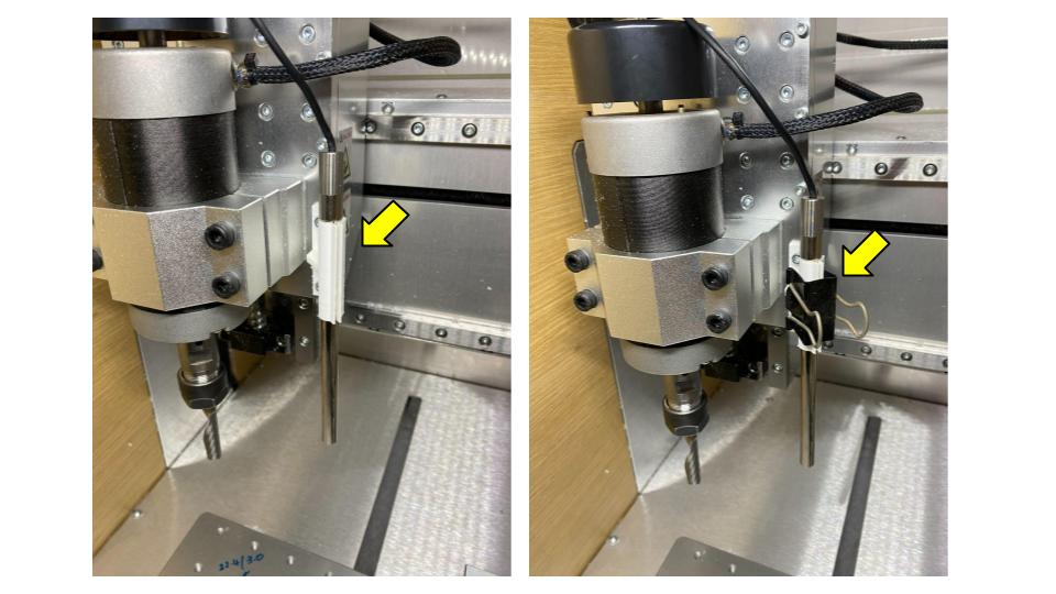
For the microscope, I am using Teslong portable MS100 USB microscope that I have gotten one for USD40. The microscope has a long and slender body (dia. 8mm) which is ideal because it wouldn’t block the movement of Z table. Simply slide the microscope onto the 3Dprinted bracket and secure it with a clip. Keep the clip on at all times.
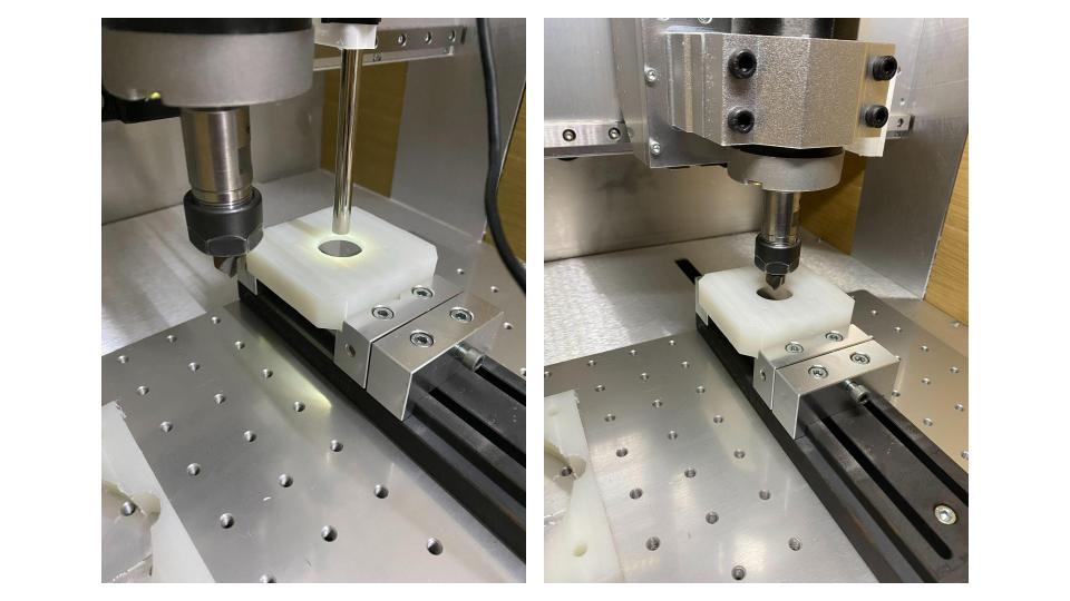
Step 4: Drill a hole on a piece of material.
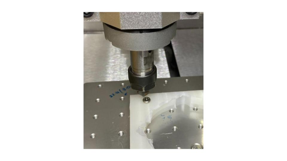
Drill a small and shallow hole on a sacrificial material. Ideally, the cutting should be V-shape or makes very small holes (dia. <3mm). Take note of the machine coordinate as you drill the hole. Record the machine coordinate as (Xdrill, Ydrill). It will be critical for calibration later.
Step 5: Move your spindle and microscope and zero it onto the drilled hole
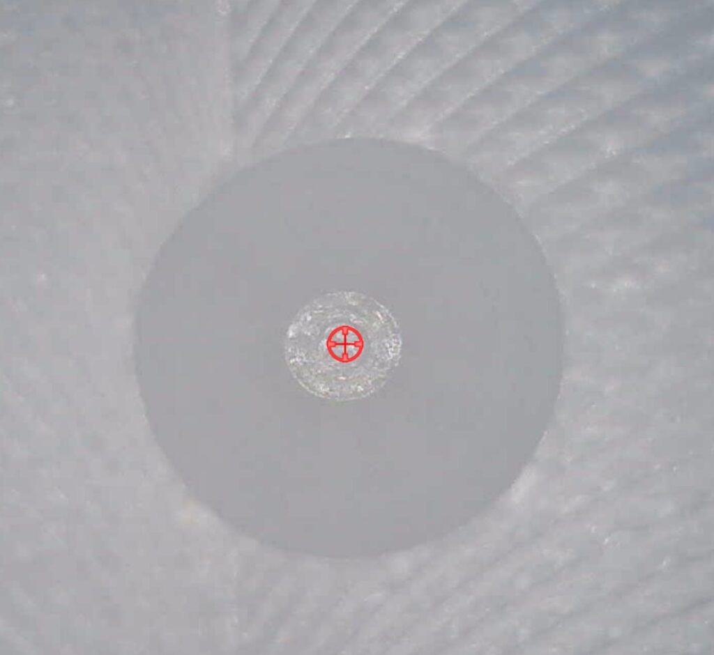
Now, with the microscope attached to your computer, turn on video view to get a live view from the microscope. To overlap a crosshair over the live view, download “Crosshair V2” from Microsoft app store for free. Now move your Z table and microscope till the crosshair is centered onto the drill hole. Record the machine coordinates as (Xmicroscope, Ymicroscope).
Step 6: Calculating Microscope offset to spindle center.
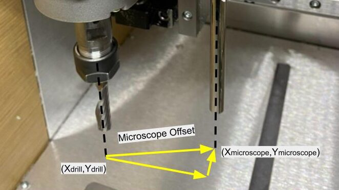
The microscope is attached at a X and Y distance (offset) away from spindle center. To get a precise measurement of the offset, we drilled a hole and move the microscope precisely till it is centered on it. The distance you need to move the microscope is the offset.
Step 7: Use microscope to catch the edges of your part circle.
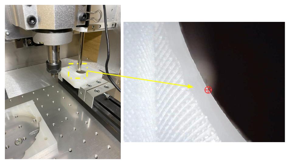
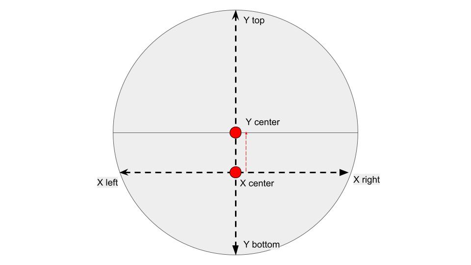
To find the circle center coordinates, you start off with finding the X coordinates. simply catch the coordinates on the left side of a circle along any Y axis, find the coordinate on the right. Then simply average it out to find the X coordinate of circle middle.
Step 8: Move microscope to middle and apply the offset
Now position the microscope to the circle center and apply the offset calculated earlier to move the spindle to the circle center. Zero your part XY coordinates and congratulation you have zero your spindle to circle center and you may proceed with next sets of milling process.