

Cycloidal disk is the main component inside a cycloidal drive. If you want to know about cycloidal drives and its working mechanism Click Here to read another article from us.
Cycloidal disk looks deceptively simple, it seems like it is made of several small circle on the rim of a larger one. However, the profile of the cycloidal disk is derived from a hypercycloid path and it gives you the best performance in terms of backlash. Hypercycloid path are rather hard to calculate but there are simple CAD technique that you can employ to create cycloidal gears without having to do all the crazy mathematics.
Step 1: Decide on key parameters
Cycloidal drives come in all shapes and sizes and before you design one, you should decide on some key parameters. The critical parameters to decide on are as follows:
1. Step down ratio – Step down ratio are the ratio of turns made by input shaft to one turn by output shaft. The higher the step down ratio, the more powerful the cycloidal drives are.
2. Eccentricity – cycloidal disk are positioned off center with respect to the input shaft. This “off-positioning” is known as eccentricity and it is around 0.5mm to 1.5mm. The values are largely determined by manufacturing capability, the size of the ball bearing used.
3. Pin size – pin are located in a circle around the cycloidal disk where it meshes against the pin. Typically, a smaller pin size allow more pin to be packed inside a cycloidal drive and improve the torque to weight ratio.
4. Cycloidal disk diameter – largely influenced by the packing of the pins. For example, if the pins are packed closely, the cycloidal disk can be shrink down.
For this tutorial, we will be using the following parameters:
1. Step down ratio = 60:1
2. Eccentricity = 0.5mm
3. Pin size = 3.0mm
4. Cycloidal disk diameter = 78mm
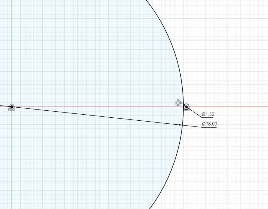
Step 2: Draw two big and one small circles
As our cycloidal disk diameter is 78mm, lets draw a big circle from the center with diameter 78mm. Beside the big circle, draw a small circle beside it. The diameter of the smaller circle is 60 times smaller than the big one because the step down ratio is 60:1.
Now draw another circle from the center all the way to the center of small circle.
Step 3 : Draw a straight line across the big circles
Divide 360 deg with step down ratio of 60 to get 6 deg. Draw a line to the second big circle with an angle of 6 deg to form an arc
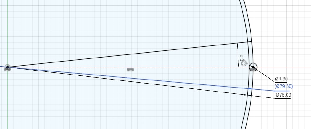
Now draw another line with 0.5 deg to that arc.
And another at 1.0 deg, another at1.5 deg and keep going till you reach 5.5 deg.
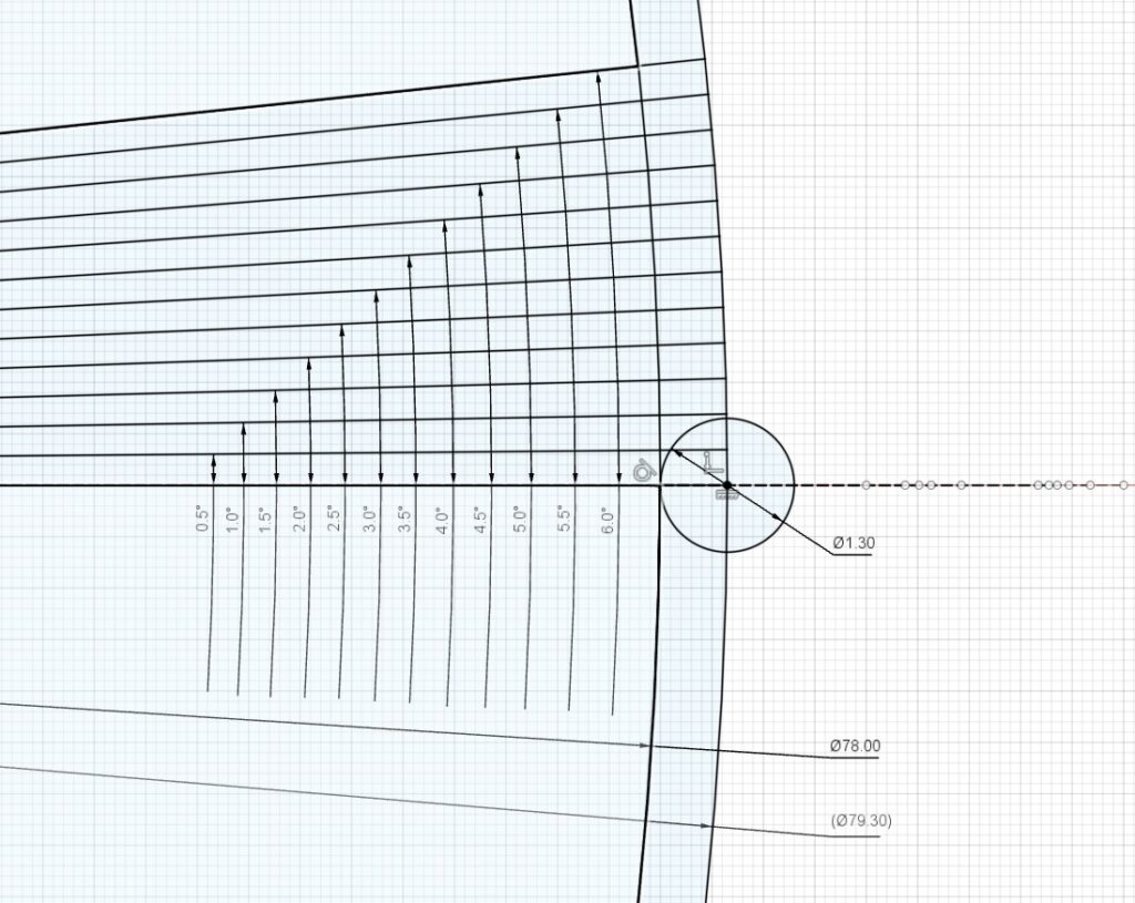
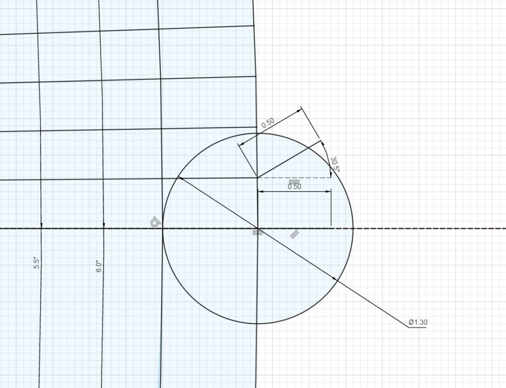
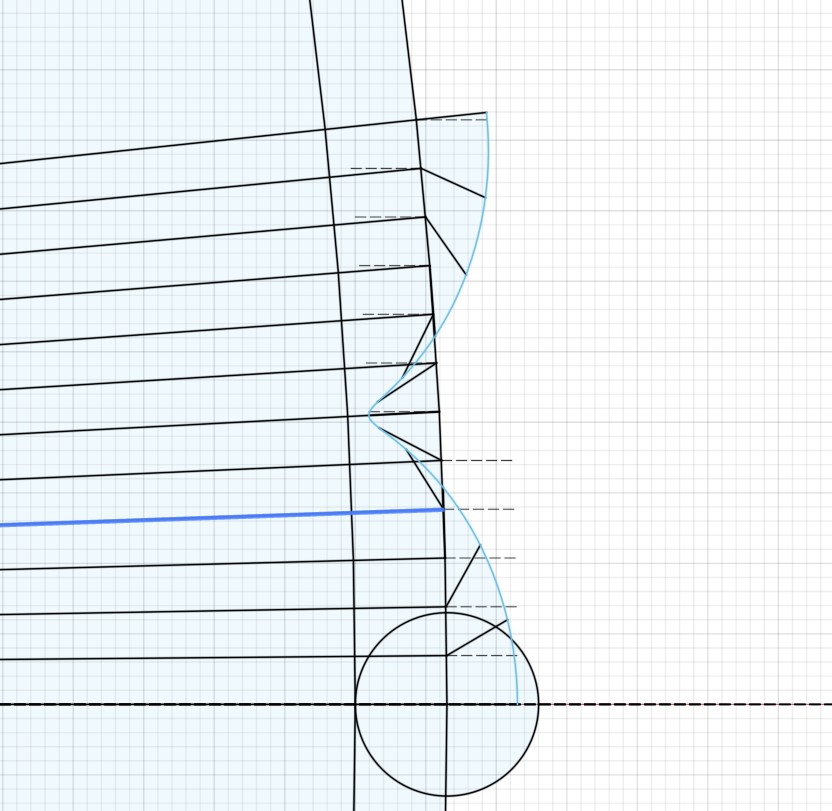
Step 4 : Draw add another line to the end
The arc should be divided into several pieces by many lines at different angle. Now let’s focus on the line with zero deg. Let’s draw a line of 0.5mm at zero deg as well. The line is 0.5mm because the eccentricity is 0.5mm.
Now for the next line at 0.5 deg, lets start another line with 0.5mm too but this time the angle of the line with be different. The angle will be at 0.5*61=30.5 where 61 is step down ratio plus one.
For the next line at 1.0 deg, let’s draw another line with 0.5mm at angle 1.0*61 = 61. and next time at 1.5 deg, the line with be at an angle of 1.5*61=91.5.
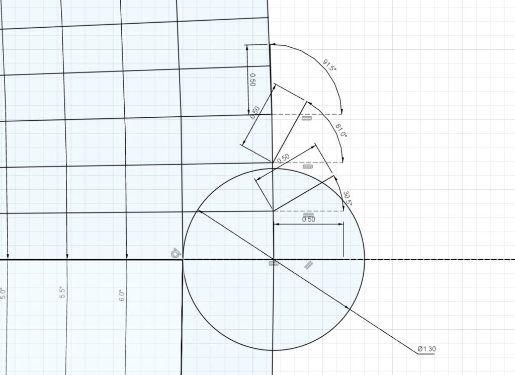
Keep repeating till the line with angle of 6 deg.
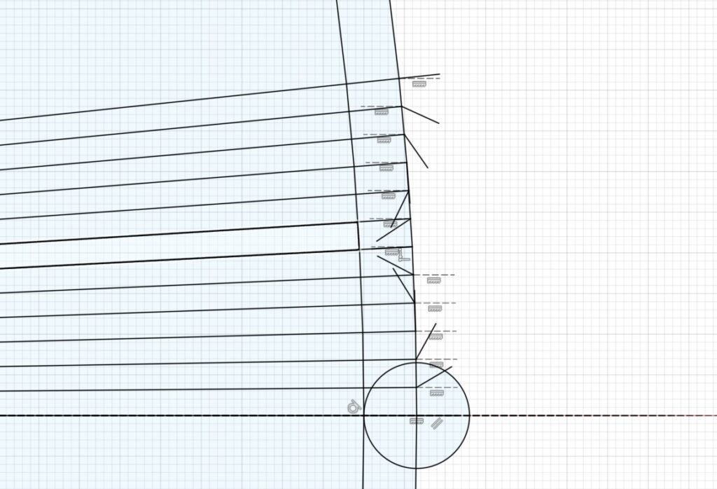
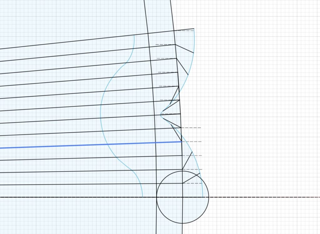
Step 4 : link all the end of the secondary lines with a spline
Do take note to link up all the secondary lines and the spline should be symmetrical around the line with angle at 3deg.
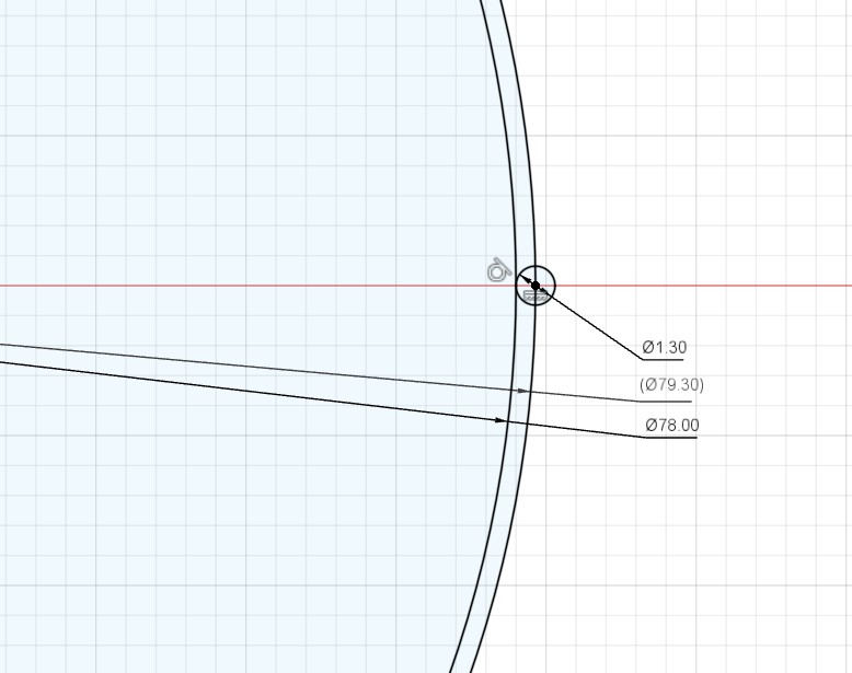
Step 5 : Offset the spline
Now offset the spline by 1.5mm because 1.5mm is half the diameter of 3mm pin.
Step 6 : do a circular pattern of the offset spline
Duplicate the offset spline around a center point by 60 times because the step down ratio is 60.
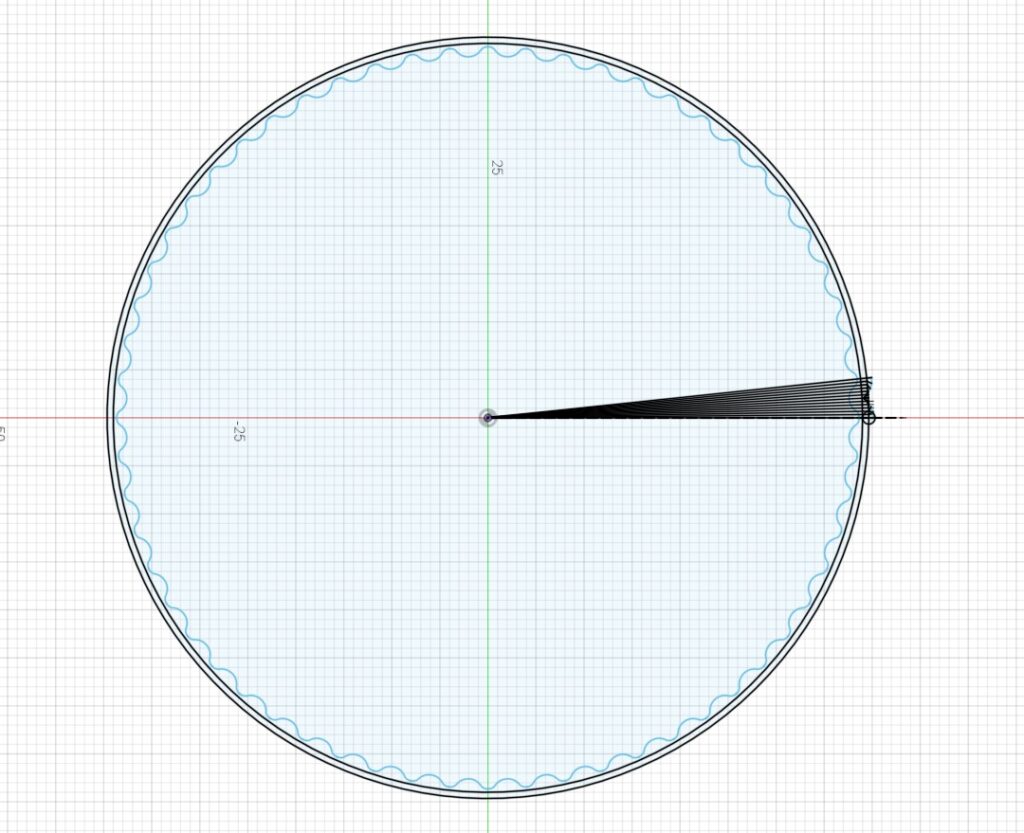
Step 6 : extrude the profile and add some holes
Now after duplicating the offset spline by 60, it should encloses a profile. Select the profile and extrude 5mm.
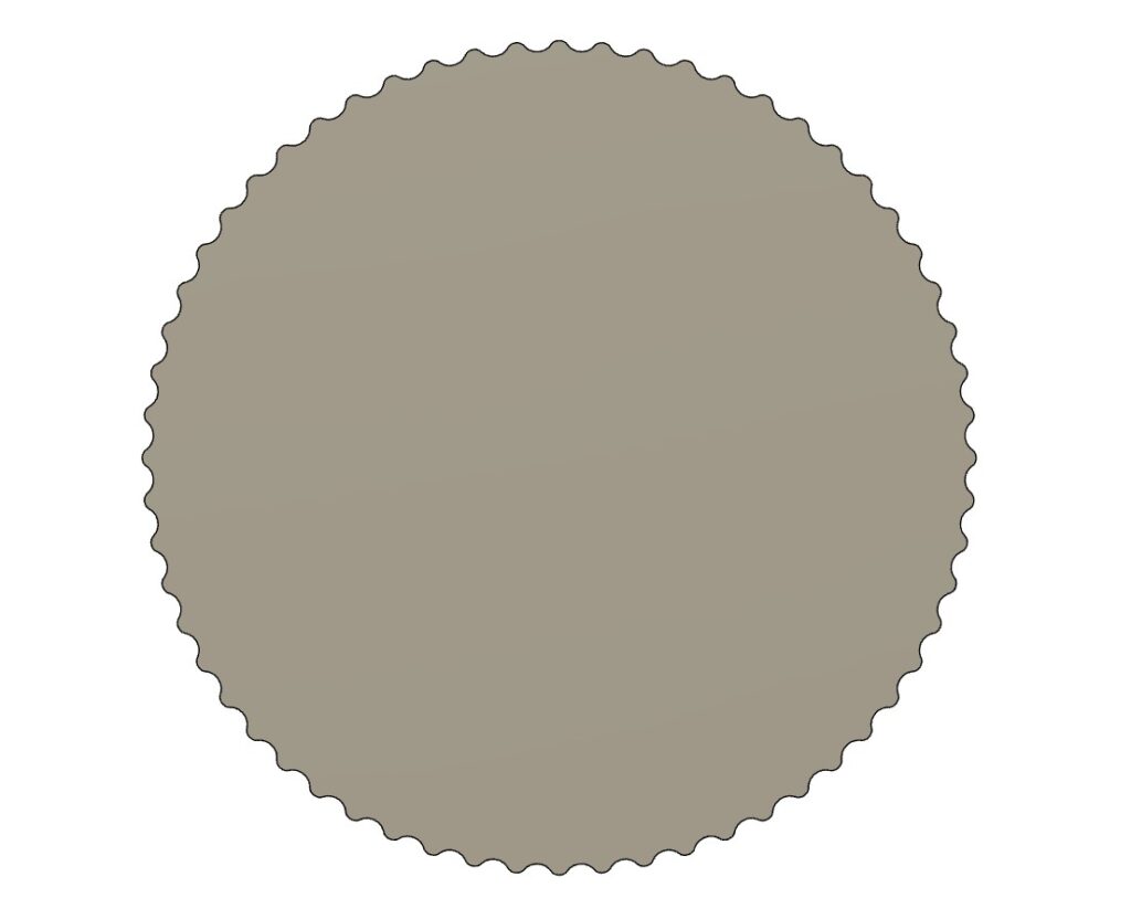
Add some holes for the bearing and for extracting torque from the cycloidal disk.
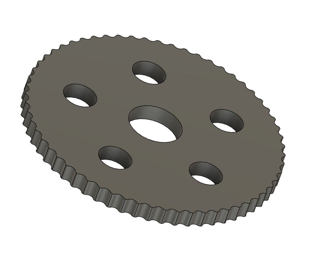
Yeap that’s it, we are done. Thanks for reading! Feel free to post any comments or questions in the comment section below.
12 comments
Step 5 : Offset the spline
how to offset ?
offset by x – 1.5mm ?
its offset of the entire spline. towards the center and not along any axis
Hi Beng!
About those holes on the output … should the center hole for the bearing be offsetted by exentricity? How about those other 5 holes … should they have a specific radius? And how about the dimensions of the output pins?
Thank you.
Hi Simon,
I have wrote a more complete tutorial on cycloidal drives, you can download the design files here https://www.ewhiteowls.com/2022/02/the-ultimate-guide-to-design-cycloidal-drives-the-beating-heart-of-robotic-arms/
*Some suggestions for your biography text:*
Hello! Welcome to The White Owls. I am the main editor for this website and I am trying to make it a great place for everyone to learn a thing or two about engineering. I am someone who has many ideas and tools in fields such as Computer Aided Design (CAD), Computer Aided Milling (CAM) and 3Dprinting which help me bring many of my ideas to fruition. I have a full time job in the metal 3Dprinting industry and I do lots of professional CAD modelling for clients. I graduated from a materials science college where I helped client understand metallurgy in metal 3Dprinting. So feel free if you have any questions on metal 3Dprinting or metallurgy!
Hey, after doing this, how do I design the rest of the gearbox? Mainly the pin positions.
Hi Viktor,
I have wrote a more complete tutorial on cycloidal drives, you can download the design files here https://www.ewhiteowls.com/2022/02/the-ultimate-guide-to-design-cycloidal-drives-the-beating-heart-of-robotic-arms/
Hi Viktor,
Thanks for your interests.
I have wrote a more complete tutorial on cycloidal drives, you can download the design files here https://www.ewhiteowls.com/2022/02/the-ultimate-guide-to-design-cycloidal-drives-the-beating-heart-of-robotic-arms/
Hi, I’m trying to design a cycloidial drive(mostly for fun) and was wondering what’s the math behind this guide. Is there somewhere I could find this?
also, this is insanely helpful either way. THANKSSS!
Hi Yadin,
I have wrote a more complete tutorial on cycloidal drives, you can download the design files here https://www.ewhiteowls.com/2022/02/the-ultimate-guide-to-design-cycloidal-drives-the-beating-heart-of-robotic-arms/
when offsetting the spline I end up with a spline that does not connect all the way to the 6 degree line. As a result when I do the pattern the profile does not close.
Hmm.. it is a little hard for me to understand. Perhaps you want to ask me over email? You can email me at contact(at)ewhiteowls.com.
BTW, I have wrote a more complete tutorial on cycloidal drives, you can download the design files here https://www.ewhiteowls.com/2022/02/the-ultimate-guide-to-design-cycloidal-drives-the-beating-heart-of-robotic-arms/
Comments are closed.