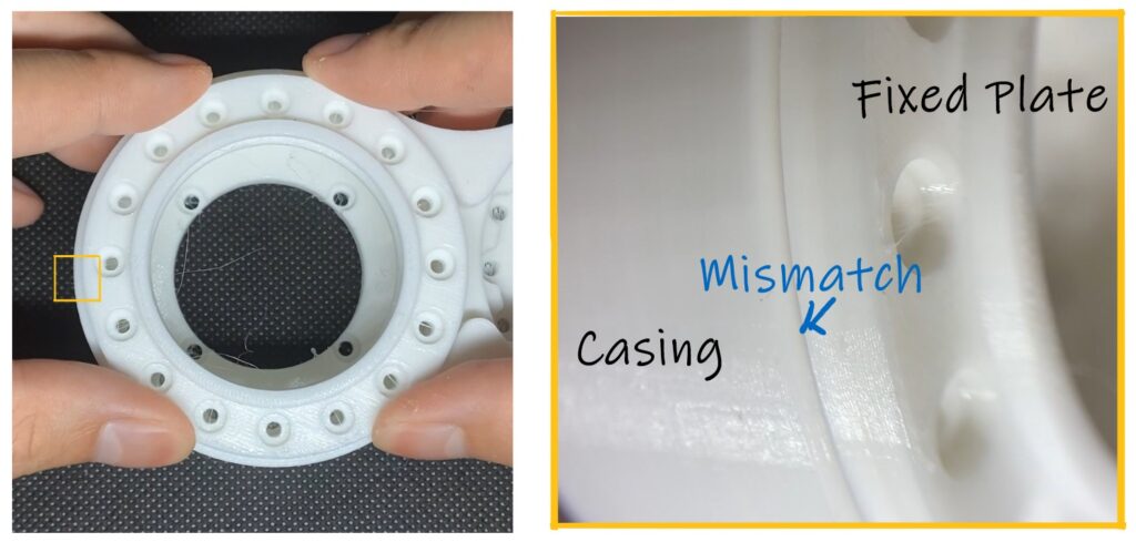
Previously we were going the different steps to create a CAD model of a slew bearing at Fusion360. The models are exported as STL and 3Dprinted overnight. Soon after the printing, I tried to assembled those slew bearing together and problems surfaced.
The slew bearing are too large to fit into the casing while the rotating plate cant fit into the fixed plate either. Why wouldn’t they fix perfectly like they do virtually?
Deviances of actual components from CAD models are actually very common. Hence, in this article we will explore the root cause of such deviances and how parametric modelling can help you save time in tuning your CAD model to perfection.
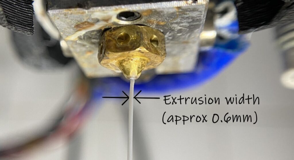
Every manufacturing techniques has its own sources of deviances and for 3D-printing, a major source of deviances is the width of polymer extrusion at the nozzle. It is around 0.6mm and it seems very minor but for precision components like slew bearing, it creates problems for assembly and smooth rotation.
As the nozzle goes around the contour (external rim) of a component to lay down material, about 0.3mm (half of extrusion width) is laid outside of the contour. As a result, your printed component is slightly oversize by 0.3mm on each side. (For example a 50mm diameter cyclinder will be 50.6mm instead because of additional 0.3mm on each side)
To compensate for a slight over-sizing of 3Dprinted parts, we can modify the dimensions slightly such that the Printed parts will be the dimension we needed. (For example, instead of modelling a 50mm diameter cyclinder, we will shrink it slightly in design to 49.4mm so the 3Dprinted part will be 50mm in diameter).
As different 3Dprinter have different extrusion width, it is necessary to modify the dimensions for different printers. It can be quite time-consuming considering how every dimensions need to be modified (every outer diameter need to be reduce and inner diameter need to be enlarged) including dimensions that need to be tuned to allow for slew bearing to work well.
Hence, today we will explore how parametric modelling can help you save tons of time.
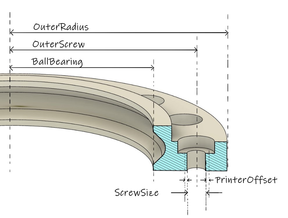
The first step to parametric modeling is identifying dimensions that requires frequent changes. Previously, the slew bearing could not fit into casing because it was oversized. So the outer radius will be changed frequently and hence we are identifying it as a parameter.
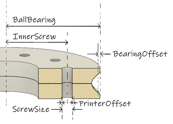
Other dimensions such as OuterScrew, BallBearing and ScrewSize are identified as parameters too since they need to be changed frequently. PrinterOffset is for adding or substracting small amount of material to compensate for extra material laid outside of model contour.
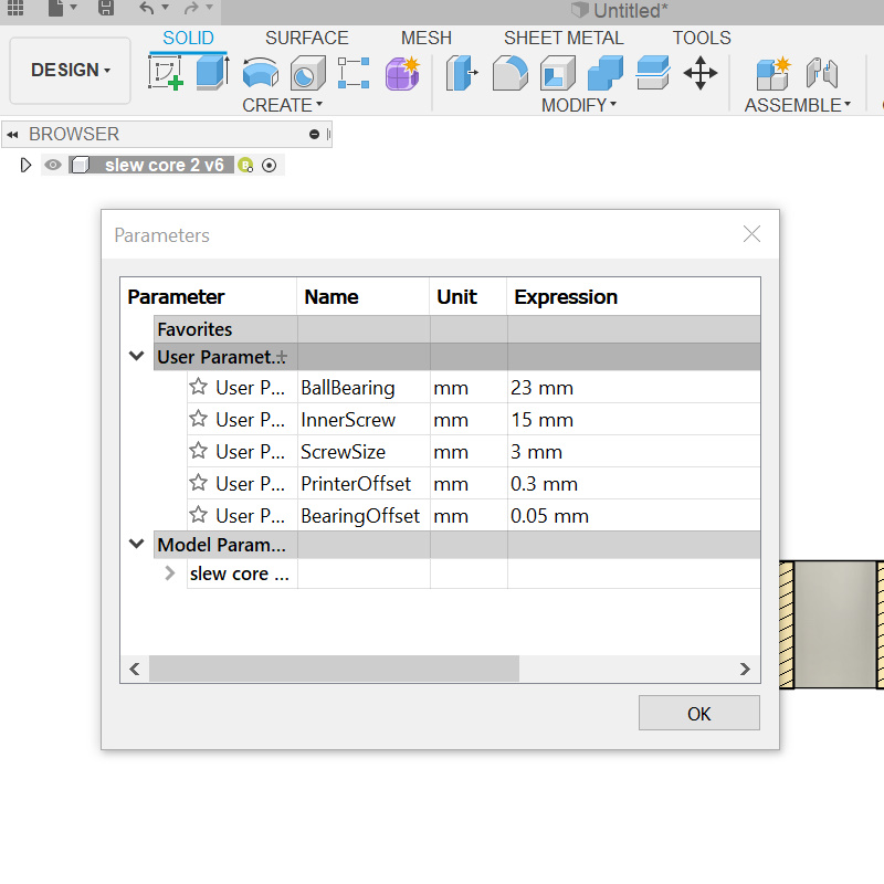
To access the parametric menus, go to “Modify” tab and scroll down to “Change Parameters”. A menu will pop up once you select the option.
So let’s key in our first parameter which is OuterRadius and set the expression to 35. Do take note of the unit and change accordingly.
Now that we have create a new parameter named OuterRadius, let go to our cross section sketches and tag the new parameters to the outer radius. Simply type in “OuterRadius” in the input box.
Now when go back to the parametric menus under “Modify” -> “Change Parameters”, we can easily change the dimension of the slew bearing without having to back to it’s sketches and spend time looking for the correct dimensions to change.
we are going to repeat the process for the rest of the parameters. We will create new parameters and then tag them accordingly in the sketches. This way we can easily change most of the dimensions in the parametric menus
Now that we have create new parameters. I am going to swop them out in the sketches, converting fixed dimensions to parameters that you can easily change in the parametric menus.
Swopping out the dimensions for screw hole position and screw diameter with parameters. Notice that I have added PrinterOffset for screw hole enlarge it slightly to compensate for extra material laid down by the nozzle. It make things easier because different printers will need different offset and by setting it a parameter, we can easily change it instead of wasting time going through every features to add/change offset for different 3Dprinters.
In general, diameter of counterbore hole are usually twice the diameter of screws. Instead of creating a new parameter for counterbore hole diameter, I can specify the diameter as (2*ScrewSize) + PrinterOffset where PrinterOffset is added to increase the hole slightly to compensate for extra material laid down by the nozzle.
Once you have swopped out all the dimensions with the parameters you have created, you can now change the dimensions very easily through the parametric menus. No more searching through every sketches and features just to change the dimensions and this will save you large amount of time.
Let’s repeat the process for the rotating plate to complete this slew bearing. One of the key parameter is BearingOffset which provide small changes to the position of the groove to either loosen or tighten the groove so that ball bearings can move in it freely. The slight separation distance is something that had to be discovered through experimentation so making it as an editable parameter will be a huge time saving.
Populating the parametric menus with new parameters.
Swopping out fixed dimensions in various sketches with newly added parameters.
There you have it, another part that is designed with parametric modelling and allows you to make changes to your part dimensions with shortest amount of time. It will be great when you are working with 10 or more parameters that need to be changed frequently and with parametric modelling, you can do it in the shortest amount of time possible.


4 comments
Good article thank you for sharing
Hi Jamal, thanks for the kinds words. If you happened to be interested in cycloidal drive, I have wrote a more complete tutorial on cycloidal drives, you can download the design files here https://www.ewhiteowls.com/2022/02/the-ultimate-guide-to-design-cycloidal-drives-the-beating-heart-of-robotic-arms/
Great content! Keep up the good work!
Hi Thanks,
If you are interested in cycloidal drives, I have wrote a more complete tutorial on cycloidal drives, you can download the design files here https://www.ewhiteowls.com/2022/02/the-ultimate-guide-to-design-cycloidal-drives-the-beating-heart-of-robotic-arms/
Comments are closed.